A flange is a common way to connect a valve to pipework and other equipment. They are easy to assemble / disassemble. Two flanges are joined together with bolts or studs and have a gasket between them.
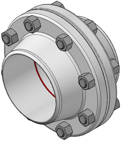
Above: Flanges clamped together
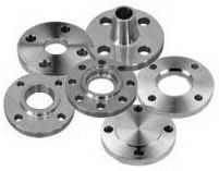
Above: Selection of flanges
A flange is specified by the following information:
a) Type and Facing: i.e. whether the flange is for example “Weld Neck, RTJ” or “Socket Weld, RF”.
b) Nominal Pipe Size: required for all flanges, usually in inches.
c) Flange Pressure Class: required for all flanges, e.g. Class 150, 300, 900, 1500, 2500 etc.
d) Standard: i.e. ANSI B16.5, BS 1560, API 6A, API 605 or ASME B16.47.
e) Material: a material specification must be stated and will be as quoted in the piping specification.
f) Pipe Schedule: only for Weld Neck, Socket Weld, Composite Lap Joint and Swivel Ring flanges where the flange bore must match that of the pipe, e.g. Schedule 10, 30, 40, ,80, 120, 160, etc.
Normally, the flange specification will be hard stamped on the flange.
Flange Standards There are several different flange standards to be found worldwide with standardised dimensions. The most common standards are ASA/ANSI (USA), PN/DIN (European), BS10 (British/Australian), and JIS/KS (Japanese/Korean).
ASA150, 300, 400, 600, 900, 1500, 2500
Metric PN6, 10, 16, 25, 40
BS10 Table D, E, F, H
In most cases these are not interchangeable (e.g. an ANSI flange will not mate against a JIS flange). Further, many of the flanges in each standard are divided into "pressure classes", allowing flanges to be capable of taking different pressure ratings. Again these are not generally interchangeable (e.g. an ANSI 150 will not mate with an ANSI 300). These pressure classes also have differing pressure and temperature ratings for different materials.
The following British Standards are also used for the standardisation of pipe joints:
BS 1560 Steel Pipe Flanges and Flanged Fittings
BS 3381 Metallic Spiral Wound Gaskets for Use with Flanges to BS 1560
BS 1832 Oil Resistant Compressed Asbestos Fibre Jointing
BS F125 Rubber Bonded Compressed Asbestos Fibre Jointing
BS 3293 Carbon Steel Pipe Flanges (over 24” NB) for the Petroleum Industry
BS 3799 Steel Pipe Fittings, Screwed and Socket-Welded for the Petroleum Industry
BS 1580 Specification for Unified Screw Threads
The following American Standards are used for the standardisation of pipe joints:
ANSI BI.1 Unified Inch Screw Threads (UN and UNR Thread Form)
ANSI BI.20.1 Pipe Threads, General Purpose (Inch)
ANSI B16.5 Pipe Flanges and Flanged Fittings
ANSI B16.9 Factory made Wrought Steel Butt Welding Fittings
ANSI B16.11 Forged Steel Fittings, Socket Welding and Threaded
ANSI B16.20 Ring-Joint Gaskets and Groves for Steel Pipe Flanges
ANSI B16.21 Non-Metallic Flat Gaskets for Pipe Flanges
API 601 Metallic Gaskets for RF Pipe Flanges and Flanged Connections
API 6A Specification for Wellhead and Christmas Tree Equipment
ANSI B16.47 Large Diameter Steel Flanges (NPS26 through NPS60)
API 605 Large Diameter Carbon Steel Flanges
ANSI B16.1 Cast Iron Pipe Flanges and Flanged Fittings
Flange Faces The flange faces are also made to standardized dimensions and are typically "flat face", or "raised face" but other types are available.
Flat Face (FF): Sealing is also by compression of a flat non-metallic gasket (very rarely a flat metallic gasket), between the phonographic/ concentric grooved surfaces of the mating FF flanges. The gasket fits over the entire face of the flange. FF flanges are normally used on the least arduous of duties such as low pressure water drains and in particular when using cast iron, cunifer or bronze alloy, where the large gasket contact area spreads the flange loading and reduces flange bending on this type of flange facing.
Raised Face (RF): Sealing on a RF flange is by a flat non-metallic gasket (or a flat metallic gasket for special applications), which fits within the bolts of the flange. The facing on a RF flange has a concentric or phonographic groove with a controlled surface finish. If the grooves are too deep (or a rough surface finish), then high compression is required to flow the relatively soft gasket material into the grooves. Too shallow (exceptionally smooth surface finish) and again high compression is required as a leak path then becomes more possible. It is important to always check the flange surface finish for imperfections which would make sealing difficult. A radial groove for example is virtually impossible to seal against.
Ring Type Joint (RTJ): Typically found on the most severe duties, for example high pressure gas pipework. Ring type metal gaskets must be used. Flange Face Finish
A flange face (raised face and flat face) has a specific roughness to ensure that this surface be compatible with the gasket and provide a high quality seal as under compression. The soft face from a gasket will embed into this finish, which helps create a seal, and a high level of friction is generated between the mating surfaces. The most used surfaces are smooth finish, Concentric Serrated, Spiral Serrated, and Stock Finish.
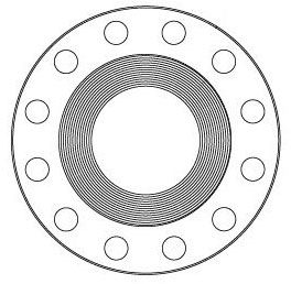
Above: Serrated raised face
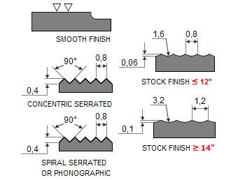
Above: ASME B16.5 face finishes
Stock Finish: This is a continuous spiral or phonographic groove. Suitable for practically all general service conditions, it is the most widely used of any flange surface finish. This finish is suitable for gaskets that have a soft conformable face. Under compression, the soft face will embed into this finish, which helps create a seal, and a high level of friction is generated between the mating surfaces.
Spiral Serrated: This is also a continuous or phonographic spiral groove, but it differs from the stock finish in that the groove typically is generated using a 90-deg tool which creates a "V" geometry with 45-deg angled serration.
Concentric Serrated: As the name suggests, this finish is comprised of concentric grooves. A 90-deg tool is used and the serrations are spaced evenly across the face.
Smooth Finish: This finish shows no visually apparent tool markings. These finishes are typically utilized for gaskets with metal facings such as double jacketed, flat steel and corrugated metal. The smooth surfaces mate to create a seal and depend on the flatness of the opposing faces to effect a seal. AARH/RMS finishes are typically smoother than 64-μin.
Lapped Finish (Cold Water Finish): Produced using a wide tool at high speeds, this finish is equivalent to a ground surface. It is mirror-like in appearance. Surfaces such as this are typically intended to be used without a gasket.
Flange Types Flange designs are available as "welding neck", "slip-on", "boss", "lap joint", "socket weld", "threaded", and also "blind" but this is more of a consideration for you if you are constructing the pipework as the flanges will already be fitted to your valve.
Flange Gaskets Flange gaskets are used to create a static seal between two flanges faces, at various operating conditions, with varied pressure and temperature ratings. A gasket fills the microscopic spaces and irregularities of the flange faces, and then it forms a seal that is designed to keep liquids and gases. Materials for gaskets can typically be divided into three main categories: Non-metallic types, Semi-metallic types, Metallic types.
There are various considerations when selecting a gasket which including Fugitive Emissions, Compatibility with the fluid, Temperature, Internal Pressure. Other special conditions i.e. vibration, erosive media, risk of the gasket contaminating the medium, corrosion of flanges, integrity, economy.
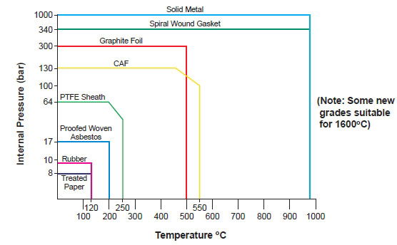
Above: Temperature / pressure guidelines for common gasket materials (NB. Always check with gasket manufacutrer for up-to-date technical information)
The following table gives examples of gasket selections based on various process parameters. Again you must consult the data sheet for the specific gasket manufacturer when making your selection.
Flange Bolts To clamp two flanges to each other bolts are necessary. The quantity will be given by the number of bolt holes in a flange, diameter and length of bolts is dependent of flange type and Pressure Class of flange. The most used bolts in Petro and chemical industry for ASME B16.5 flanges are stud bolts.
 Note: The minimum S is typically 1/3rd times the bolt diameter
Common bolt specifications are abbreviated as follows:
a) Normal alloy steel: Grade B7 bolts x Grade 2H nuts.
b) Low temperature alloy steel: Grade L7 bolts x Grade L4 nuts.
c) Austenitic stainless steel: Grade B8M bolts x Grade 8M nuts.
Bolt Tightening To obtain a leak-free flange connection, a proper gasket installation is needed, the bolts must be assign on the correct bolt tension, and the total bolt strength must be evenly divided over the whole flange face.
The first pass, lightly tighten the first bolt then move directly across or 180 degrees for the second bolt, then move 1/4 turn around the circle or 90 degrees for the third bolt and directly across for the fourth. Continue this sequence until all bolts are tightened.
Flange Face Re-Machining Flange face re-machining may be carried out in order to repair the sealing face of a flange which has corroded, deteriorated or otherwise been damaged. The extent of any re-machining must be such that the flange dimensions still remain within the tolerance specified in the flange manufacturing standard, ANSI B16, API 6A, BS 1560, etc. machining which reduces the flange dimensions to below the minimum specified dimensions will result in possible leakage.
Flange Identification Normally, the flange specification will be hard stamped on the flange. In the case of existing plant, the information may not be legible and it is then necessary to identify the flange by visual observation and physical measurement.
a) Visual Observation: required to identify the type of flange and type of gasket used.
b) Physical Measurement: required to identify the nominal bore and the class of the flange. Check the number of stud bolts, stud bolt diameter, stud bolt Pitch Circle Diameter (PCD) and the flange thickness. Compare these figures with standard flange data as found on our Flange Tables.